
M
0
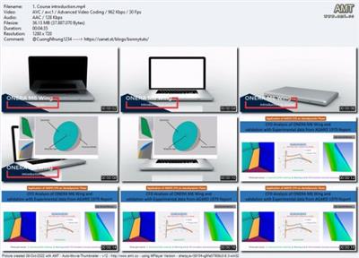
CFD analysis of ONERA M6 wing - Part 1 Geometry modeling
Published 10/2022
MP4 | Video: h264, 1280x720 | Audio: AAC, 44.1 KHz, 2 Ch
Genre: eLearning | Language: English | Duration: 13 lectures (2h 1m) | Size: 1.2 GB
CAD modeling of ONERA M6 wing in Solidworks and domain creation in Spaceclaim that will be used for subsequent CFD Study
What you'll learn
Understanding of test case and getting important data about ONERA M6 wing such as airfoil coordinates, 3D details etc.
Creating accurate CAD model using Solidworks as per specifications given in AGARD report
Creating full model and domain in Spacleclaim ready for meshing in ICEMCFD
Creating named selections/boundary conditions for different parts
Requirements
Basic knowledge of Aerodynamics
Basic knowledge of CAD modeling and Solidworks
Basic knowledge of Spaceclaim
Description
ONERA M6 is a classical test case for CFD validation. Although geometry is simple, but the flow field involves complex flow features such as transonic flow (Mach No. 0.7 - 0.92) with shocks, boundary layer separation etc. The ONERA M6 wing was designed in 1972 by the ONERA Aerodynamics Department as an experimental geometry for studying three-dimensional, high Reynolds number flows. ONERA is a swept back wing, with half span. It is external third of M5 Wing without twist.
In this three part course series, you will learn about the conducting CFD analysis of ONERA M6 wing as per data given by AGARD AR 138 1979 by Schmitt, V. and F. Charpin.
Part 1 (Present course) deals with geometry modeling in solidworks and domain creation in spacelaim according to above reference. Part 2 will teach to create high quality hexa meshing for the same wing in ICEMCFD. With consideration to resolve boundary layer and shock wave. Third part will teach you about conducting high quality CFD analysis in Fluent and post processing of data such as lift and drag coefficient. And also coefficient of pressure at various span locations.
Learning outcomes of this course
1. At the end of this three part course/tutorial, student will be able to perform CFD simulation of exteneral, viscous, compressible flow around 3D geometry at transonic conditions using various turbulence models and appropriate Y+ values.
2. Student will be able to understand/learn all processes involved in high fidelity CFD analysis such as geometry creation, meshing, CFD setup, solution and post processing.
3. Student will be able to validate CFD results against experimental data from AGARD report.
4. Following things will be covered
Geometry generation in Solidworks
Hemisphere domain in Spaceclaim
Hexa meshing in ICEMCFD
Mesh import, boundary conditions specification, material properties, solver settings, report definitions, hybrid initialization etc.
Steady state, 3D Reynolds-Averaged Navier-Stokes
Spalart-Allmaras, K-Epislon, Shear Stress Transport SST and transition turbulence models
2nd order upwind flow scheme
Compressible, implicit solver
No slips wall, Symmetry and pressure Far-Field boundary conditions
Convergence acceleration using latest options in Fluent 2022 R1
Parallel solver
Post processing of results
Validations of results against experimental data.
solution convergence assessment based on lift and drag coefficients.
Resources
You will get following resources in this course
1. All power point slides
2. AGARD Report
3. All files including geometry, domain, hexa mesh, solved case and data files, excel file for data, aerofoil coordinates and also geometry from NASA.
Problem Setup
This problem will solve the flow past the wing with these conditions
Freestream Temperature = 288.15 K
Freestream Mach number = 0.8395
Angle of attack (AOA) = 3.06 deg
Reynolds number = 11.72E6
Mean aerodynamics chord = 0.64607 m
These transonic flow conditions will cause the typical "lambda" shock along the upper surface of the lifting wing.
Who this course is for
This course is intended for the students who want to learn about CFD modeling and CAD modeling of ONERA M6 Wing
Any body who is interested in learning advanced level CFD analysis
Download link
rapidgator.net:
You must reply in thread to view hidden text.
uploadgig.com:
You must reply in thread to view hidden text.
nitroflare.com:
You must reply in thread to view hidden text.
1dl.net:
You must reply in thread to view hidden text.
")